MANUAL/AUTOMATIC TRANSMISSION 2-BUTTON
REMOTE STARTER WITH VIRTUAL TACH SYSTEM
(AS PRG-1000 COMPATIBLE)
Notice
The manufacturer will accept no responsibility for any electrical damage resulting from improper installation of the product, be
that either damage to the vehicle itself or to the unit. This unit must be installed by a certified technician using all safety devices
supplied. Please note that this guide has been written for properly trained Autostart technicians: a certain level of skills and
knowledge is therefore assumed. Please review the installation guide carefully before beginning any work.
Warning
Before installing the unit, if installing on a vehicle with a manual transmission, test that the OEM Door Switch contacts of the
vehicle work well, and that the Parking Brake system operates properly. If installing on a vehicle with an automatic
transmission, test that the vehicle does not start when the gearshift lever is in the “Drive” position. If it starts in gear, reset the
remote starter to manual transmission.
Doc#: 110530 Rev.: 1.0 © 2011 - CT-3271 - - FcN - Canada
QUICK INSTALLATION GUIDE
To obtain a copy of the full installation guide, please visit our website at www.prostart.org
TableofContents
Manual or Automatic Transmission setup .......... 1
Push To Start ...................................................... 2
Hybrid Option ...................................................... 2
Entering Programming Mode .............................. 2
Programming the transmitter to the module ....... 3
Entering Programming Options .......................... 3
Programming Options 3
Setting up the TACH ........................................... 4
Virtual Tach adjustment 4
Multi-speed Tach Programming 4
Transponder Programming ................................. 5
Resetting the Module .......................................... 5
Bypass ................................................................. 5
SmartStart™ ....................................................... 5
Testing ................................................................. 5
Diagnostics – Parking Light Flash Table ............ 6
Diagnostic table for start failure. 6
Diagnostic table for shutdown. 6
The wiring diagram is at the middle of this guide.
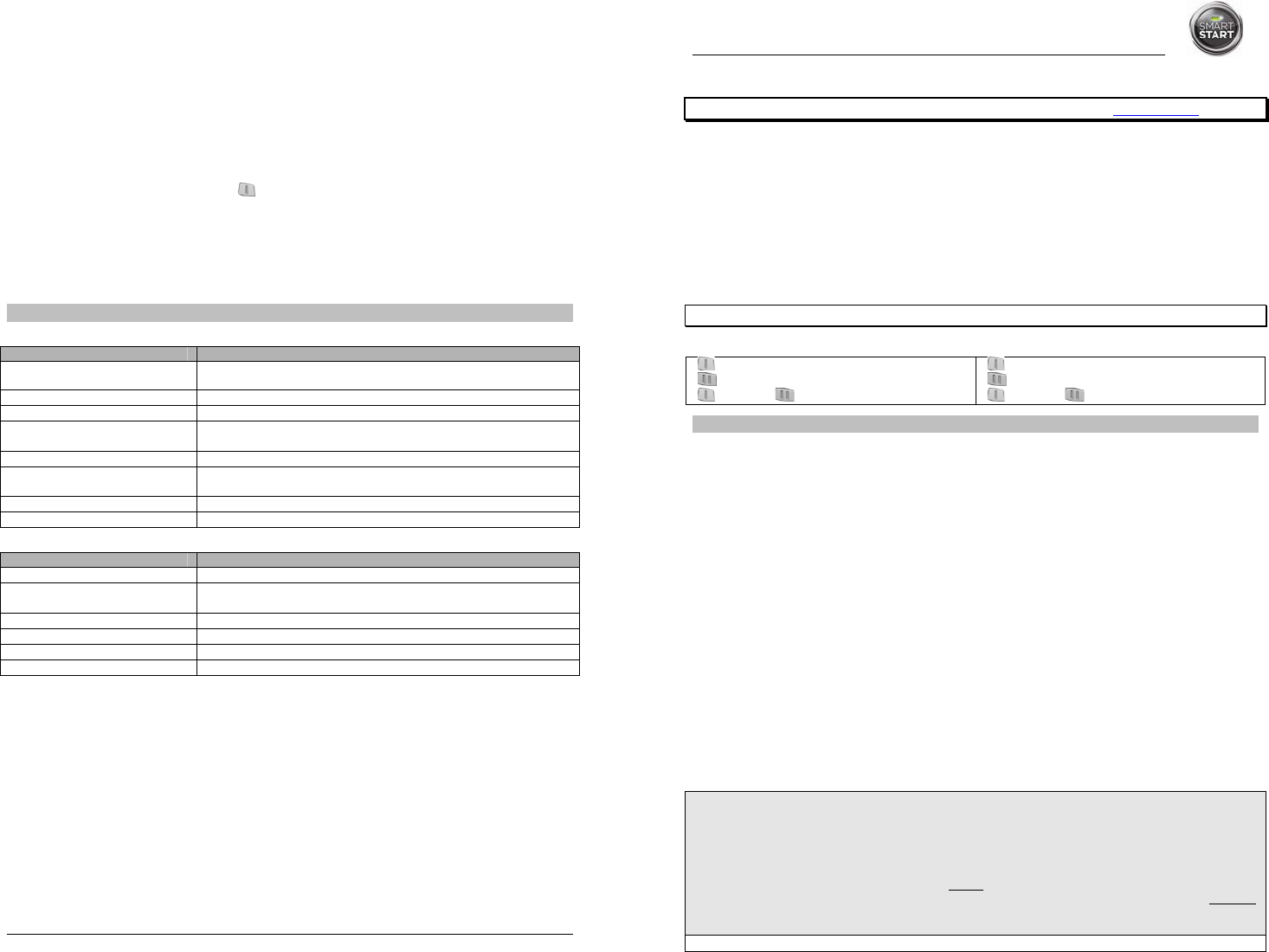
The functions of the transmitter are as follows:
Remote Function OPTION 1 Remote Function OPTION 2
BUTTON: STOP
BUTTON: START/STOP
BUTTON & BUTTONS (together): TRUNK
BUTTON: LOCK/UNLOCK
BUTTON: START/STOP
BUTTON & BUTTONS (together): TRUNK
MANUAL OR AUTOMATIC TRANSMISSION SETUP
This module may be installed on vehicles with manual or automatic transmissions. It is originally configured for manual
transmissions. If the vehicle you are working on is automatic, it is mandatory to make a few quick and easy modifications before
the unit is connected. In the event that the configuration requires changes afterwards, a complete reset will be necessary before
those changes become effective.
To install this unit in a vehicle with a MANUAL transmission:
1. Make sure the Yellow loop on the PC board is connected.
2. Connect the Orange handbrake wire located on the 12-pin harness to the vehicle handbrake switch.
3. Connect the Blue/White (+) door input OR the Grey (-) door input wire located on the 12-pin harness to the vehicle door
pin wire, which monitors all the doors of the vehicle (only use 1 of the 2 door trigger inputs).
4. Make sure the Purple TACH wire is plugged in – the TACH wire MUST be hooked up when the module is set for a
manual transmission.
5. Make all your regular connections.
6. Power up the unit by first inserting the 5-pin connector, then the 6-pin connector and finally the 12-pin connector. The
parking lights will flash 4 times.
7. When learning the transmitter, the parking lights will flash 5 times quickly.
8. Upon the first successful remote start, the system will lock the transmission settings to manual mode.
To install this unit in a vehicle with an AUTOMATIC transmission:
1. Cut the loop on the pc board (Yellow wire).
2. Make sure the Orange handbrake wire is not connected to any of the vehicle circuits.
3. Make all the regular connections.
4. Power up the unit by first inserting the 5-pin connector, then the 6-pin connector and finally the 12-pin connector. The
parking lights will flash 4 times.
5. When learning the first transmitter, the parking lights will flash 5 times quickly then give 2 slow flashes.
P.6 Quick Installation Guide
Parking brake shutdown circuit (manual transmissions only). With the vehicle running under remote start,
disengage the parking brake. The engine should shut down immediately. If the engine continues to run, check the
parking brake switch connection.
OEM alarm control. Make sure the module is able to arm and disarm the OEM alarm (if applicable).
Door locks and trunk testing. Make sure each of these options respond to the transmitter (if installed).
Door pin shutdown circuit (manual transmissions only). Make sure the system exits ready mode when each
door is opened. (Test each door.)
Starter kill option. Sit inside the vehicle with all doors closed. Arm the vehicle, then try to start the engine with the
key. The engine should not start. If the engine starts, rewire the starter kill to reach proper operation.
Valet mode. Make sure the remote car starter is able to properly enter and exit valet mode. When setting the remote
car starter into valet mode, pressing the BUTTON will lock the doors without activating the starter kill. (Refer to
the user guide for further information on valet mode.)
Idle mode. Make sure the vehicle properly enters and exits idle mode.
Door. Make sure that when the system is armed, opening any door or opening the trunk will trigger the alarm (if
installed).
Most comebacks are the result of misunderstandings about how a product works or performs. Take the time
to properly explain all functions and features to the customers before they leave the premises. Doing this
will save time and money.
DIAGNOSTICS – PARKING LIGHT FLASH TABLE
Diagnostic table for start failure.
Parking lights flashes Cause
1
(Manual transmission only)
x Ready mode is not activated.
1 slow
2 quick
x The system is set to valet mode.
1 slow
2 quick
2 quick
x The system is in Home valet
3
(Automatic transmission only)
x The parking brake is active.
x Yellow loop is connected.
4
x Brake wire is active.
5
(Manual transmission only)
x Tach signal is not learned.
6
x A tach signal is detected before Ignition.
10
x Hood wire is active.
Diagnostic table for shutdown.
Parking lights flashes Cause
1
x Runtime has expired.
2
x Shutdown by remote.
x Ready mode is activated.
3
x Failed start (VTS or tach failure, depending on selected).
4
x Brake shutdown.
10
x Hood shutdown.
Flash for 30 sec.
x Panic mode.
Note: The installer can also use the PRG-1000 to diagnose shutdown and remote start failures. Refer to the
PRG-1000 manual guide.


 (12 pages)
 Manymanuals.com
 Manymanuals.de
 Manymanuals.fr
 Manymanuals.it
 Manymanuals.pl
 Manymanuals.cz
 Manymanuals.es
 Manymanuals-pt.com
Commentaires sur ces manuels